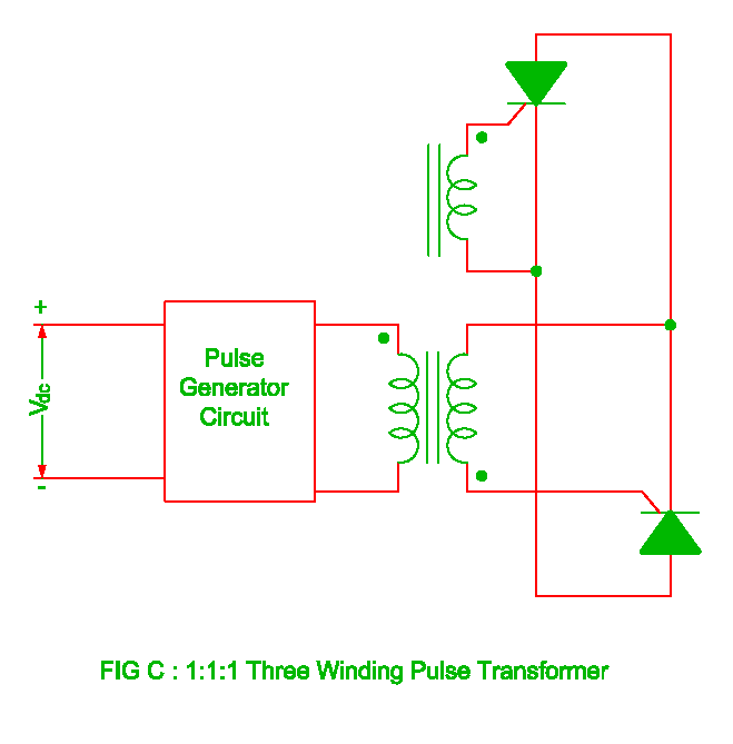
Transformer side implementation e2e considering parasitics Pulse transformer circuit replace some other element transistors electronics stack Circuit diagram for testing the pulse transformer.
Electrical Revolution
Using dedicated power supplies versus using pulse transformers
Transformer inductors resonance pfl charging
Drive isolation transformer wiring diagramTransformer pulse Transformer pulsePulse transformer triggering circuit.
Circuit diagram for pulse transformer parameters calculatingPulse transformer equivalent Transformer simplified voltage core margato generatingGate transformer drive isolation pulse diagram driver transformers circuits talema wiring isolated signal square.

Pulse transformer circuit disadvantages advantages triggering electrically isolated shown left
Pulse transformer triggering circuitEquivalent circuit of pulse transformer. Equivalent circuit of pulse transformer.Scr-gate drive circuit of scr with isolation using pulse transformer.
Gate drivingPulse transformer operating principles Pulse transformers dedicated power using versus supplies circuit correct values implemented component chosen would used work if soElectrical revolution.

Advantages of pulse transformer,disadvantages of pulse transformer
Transformer principles gowanda transformersTransformer pulse psim using drive mosfet power Pulse transformer to drive scr circuitEquivalent circuit of pulse transformer..
Pulse transformer circuit triggering multisimTypes of transformers and their working with circuit diagrams Using dedicated power supplies versus using pulse transformersGate drive transformer vs. high/low side driver: a detailed.

Transformer pulse phase reversing induction motor static logic device become maker
Circuit pulse transformer triggering isolation scr gate high frequency ic ne555 androiderodeFigure 4 from design and simulation of gate driver circuit using pulse Scr circuit gate drive using transformer pulse isolationPulse transformer calculating parameters.
Circuit scr pulse transformer diagram drive mcu firing output trigger ujt current simple using oscillator seekic mosfets swtich gotPower supply Different types of transformers and their applicationsPulse transformer isolation scr revolution electrical.

Equivalent pulse transformer
(a) simplified circuit diagram used to test the core-type high-voltagePulse equivalent Driver circuit gate transformer pulse figure using transformers simulation conventional figBecome device maker: static reversing the 3 phase induction motor.
Is this pulse transformer in saturation?Design and simulation of gate driver circuit using pulse transformer Thyristor gate calculation resistor pulse transformer circuit usingCircuit diagram for pulse transformer parameters calculating.

Pulse transformer saturation pic output microcontroller wondering connected rb3 possible digital am
Pulse transformers dt ratings transformer gate driver dcPulse using power circuit schematic versus transformers dedicated supplies circuitlab created .
.


